EGI Wiring
Wiring for the Datsun A14/A15 EFI (EGI) system.
| class="wikitable navbox" style="border:0;" | |
| Datsun Factory Fuel Injection | |
| EGI main article | |
| EGI Wiring | |
| EGI Photo Index | |
| A14E Service Manual | |
| Introduction of GX-E | |
| 200SX EFI |
| class="photobox" style="width: 185px; height: 139px"| 
|}
Overview
Wiring here is based on Datsun S110 (Silvia/Gazelle/240RS), specifically the 1981 USA "200SX" version. See 200SX EFI.
The simplified "4-wire" setup, which assumes you are using a factory wiring harness cut out of a donor car, is:
- IGN
- START
- GROUND/EARTH
- FUEL PUMP
Engine Harness

Engine harness
- Injectors
- Air Regulator (air bypass system -- for idle speed)
- EGR/VVT vacuum-cut switch (can be disconnected)
- Throttle Sensor (Throttle position sensor)
ECU Wiring
22612-N7801 to 0681 (no O2) 22612-N8500 from 0781 (O2 sensor)
Wires from ECU to engine compartment OUTPUTS * Injector outputs (4) Wires from engine compartment to passenger compartment INPUTS * Power (from EFI relay) * coil negative (tach sense) * air flow meter * air temp sensor (in flow meter) * throttle valve sensor * START wire for ignition switch (to indicate when to do cold-start enrichment) * water temp sensor (on underside of intake manifold) * O2 sensor (not used on early B310)
EFI Relay
B310 EFI Relay

RELAY ASSY, EGI 25230‐89971 A14E -7910 25231‐89966 A14E 7910-8010
B310 A14E wiring diagram
https://i297.photobucket.com/albums/mm219/ddgonzal/Datsun%201200/wiki/1978_A14E/034aRelayECU_1.jpg
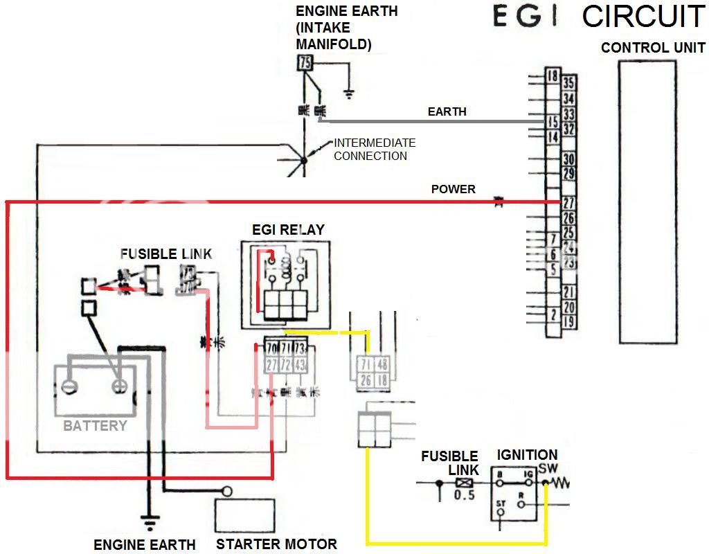
B310 ECU PIN 27 POWER 15 EARTH
original
https://i297.photobucket.com/albums/mm219/ddgonzal/Datsun%201200/wiki/1978_A14E/034aRelayECU.jpg

S110 EFI Relay
Needed: One relay, one Fusible Link, 20 gauge Power & Ground wires
There is a dedicated Fusible Link for the ECU

 25230-C9900 RELAY ASSY [or 25230-C9907] * SWITCH: * C: BW wire from IGN switch * E: B ground/earth * D SOURCE: from Brown fusible link to Light Green/white * B OUTPUT: LgR to Red wire to ECU #207
200SX factory wiring diagram

Fuel Pump Wiring
Pump has 2 wires * B: earth/ground * LgR (Light Green with Red stripe): pump power
S110 uses 3 relays: FUEL PUMP RELAY 1, FUEL PUMP RELAY 2, FUEL PUMP RELAY 3. The multiple relays are for safety. Relay takes inputs from Alternator, ECU, and Oil pressure switch. Pump will shut off if engine dies, because Oil and Charge will stop working, the relays shut the pump off. This is important for safety in a crash.
Fuel Pump Relays
At the minumum to protect the wiring, you need one relay for the fuel pump. It draws over 5 amps, so you don't want to run it directly through the IGN switch at the risk of burning out the switch contacts or overloading the existing small IGN wiring.
Although you could use the minimum one relay, for safety the Datsun factory system uses a chained system of three relays.
Nissan 5-blade relay * 25230-C9900/25230-C9907 RELAY-FUEL PUMP JIDECO * 25230-C9905 RELAY-FUEL PUMP NILES
Fuel Pump Relay 1
Pump On/Off: this relay engergizes the Fuel Pump and Air Regulator, but Relay 2 can open the circuit.
* SWITCH: * C: (Lg) from Fuel Pump Relay 2 OUTPUT (Lg) * E: Earth/ground * D SOURCE: BW from IGN switch * B OUTPUT: LgR * to Air Regulator LgR * to Fuel Pump LgR
Fuel Pump Relay 2
Pump Power: This relay is wired NORMALLY CONNECTED (i.e. when off). It passes on to Relay 1, but when Relay 3 is on it disconnects.
* SWITCH OFF: * C: L from ACC L FUSE 15A * E: (switched ground) LW from Relay 3 OUTPUT (LW) * D SOURCE: BW from IGN switch * A OUTPUT NORMALLY CONNECTED: Lg to Relay 1 SWITCH(Lg)
Fuel Pump Relay 3
Pump Cutout: This disconnects the Pump Feed relay in certain scenarios.
* SWITCH: * C: BW from IGN switch * E: WR to DIODE to Alternator WR * D SOURCE: YW to GROUND/EARTH via Oil Pressure Switch * B OUTPUT: LW to Relay 2 SWITCH (LW)
200SX Oil Pressure Switch is a dual-wire type because 200SX has an oil pressure gauge, but we only need the typical sensor used on all A-series engines. If you want to use a Oil Pressure Gauge, you can fit this sensor.
25070-80W0 DUAL OUPUT * On/off pressure switch for OIL light & fuel pump relay * Resistor sensor for gauge
Injector Wiring
How the injectors are wired depends on the ECU you use. The following is information on Nissan ECUs. If using Motec, Haltech, etc. see their instructions.
Here's the actual schematic for Dropping Resistor wiring from the 1978 A14E Service Manual. It shows a 5-pin resistor pack.
https://i297.photobucket.com/albums/mm219/ddgonzal/Datsun%201200/wiki/1978_A14E/EGI_harness_.jpg EGI Harness
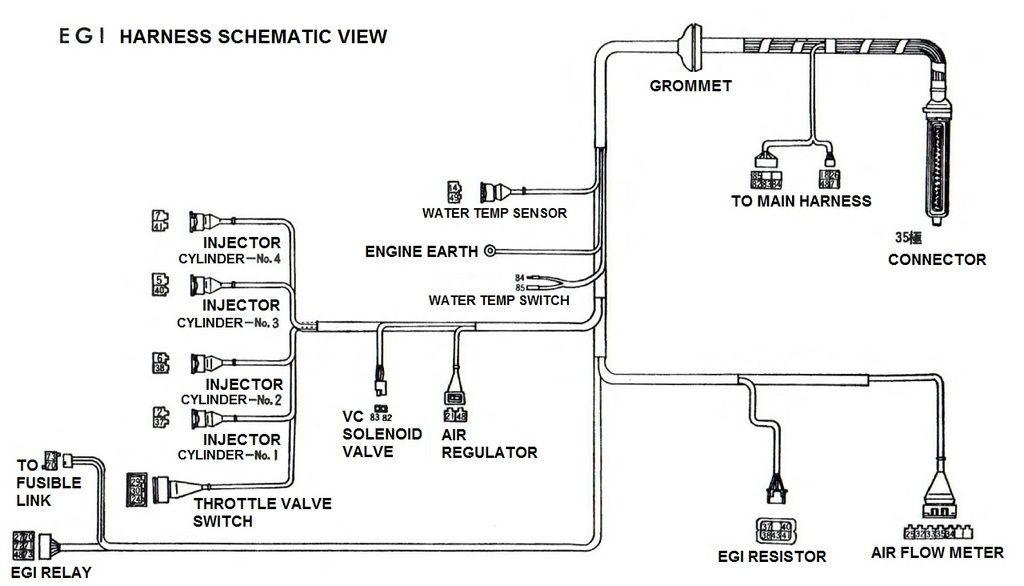
1981 S110 USA (Z20 engine) uses the same 5-wire Dropping Resistor

- Both systems provide 12V to the resistor pack common pin.
- The injectors are grounded via the four ECU injector pins.
- B310 (A14E) 12V is supplied via dedicated Fusible Link and ECU/ECCS relay
- S110 (Z20E) 12V is supplied via dedicated Fusible Link (always hot)
1978 A14E
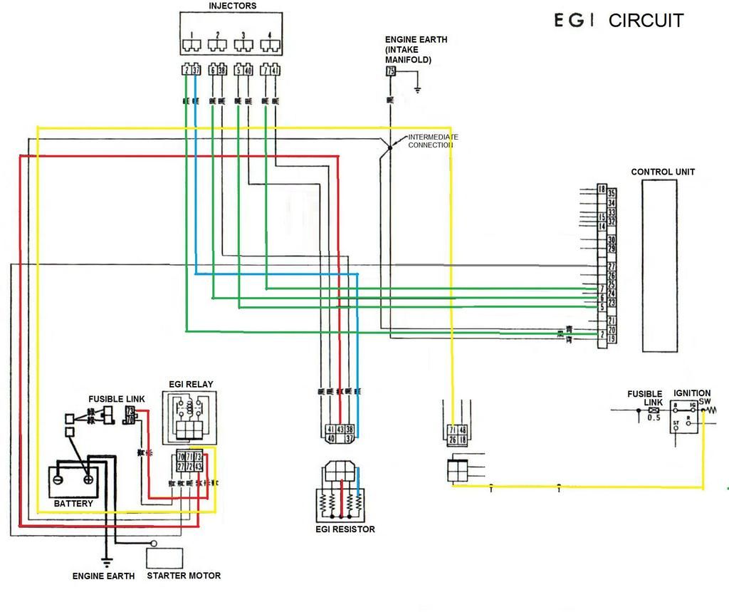
Dropping Resistor
Fuel injector dropping resistor: 2.35 ohms resistance.
File:20100829190547DSC00753x.jpg

¤