Wiring Diagram
WARNING: Wire colors can vary by year, model and country. Please double-check the wiring in your Datsun 1200 before connecting parts according to this article. You don't want to burn something up! Use a voltmeter or test light to confirm the circuit behavior. There are even one or two mistakes in the factory diagrams.
Overview
Nissan wiring diagrams come in:
- The Factory Service Manual
- The Service Bulletins

- Aftermarket Repair manual, such as Haynes, Gregory's, Chilton and Clymer. Not all include a diagram but older ones did.

Market Differences
Country/Regional Market differences include:
- Hazard (emergency) Flasher system
- JDM: Hazard system with single Flasher
- USA: Hazard system with separate Hazard Flasher and T/S Flasher
- Export non-USA: No Hazard System (OPTION for later Australia utes)
- Headlight switch for Australia has two-position dimmer and positions act differently
B110
Worldwide
Datsun 1200 except USA & Canada
 1362 x 1119 (1.4 megapixel)
UK 1200 ?
for manual transmission
 > 1280 x 864 (and blurry)
USA
USA Intro Diagram.
 1152 x 768
1971
1971 USA, same as or very close to JDM

 two pics each 639 x 918 (and blurry)
1972
Minor changes from 1971, mostly additions.

 Two-part high res 1519 x 1024
RED: Changes from 1971
- Automatic Choke and relay
- dash lamp labeled "IGN" instead of "CHG"
- ACC circuit added to Ignition Switch (radio and heat glass)
- Heated Glass added to diagram
- Heater and switch wired differently
GREEN: New for 1972 emission control for manual transmission vehicles
- cutting valve solenoid (for TCVAS)
BLUE: Automatic Transmission models only
- Kick Down switch on gas pedel & solenoid on transmission
- Inhibit Switch (Park/Neutral switch on transmission)
1973
USA 1973 Manual Transmission
CAUTION: different from 1972-1972, and from non-USA

 two pics each 639 x 918 (and clear)
New for 1973
- anti-diesel solenoid
- Neutral Switch detect switch
- Heater illumination
- seat & retractor switch (?)
- Ballast resistor deleted (?)
- Speed switch & throttle opener solenoid (?)
Clarified
- "Indicator Lamp" now labled "Indicator Lamp (A/T)"
- "Heat Glass" hnow "rear defroster"(Canada only) switch & defroster and shows 10A fuse
Changes from 1972
- Heater and switch wired differently
- Door switch changed to two-pole with color change from BR to B
- warning buzzer colors from R to BR
- warning switch from R to L
- Wire colors rationalized
- TCVAS fuse wire color from BW to L
- Left t/s color body/rear harness (makes it consistent with front harness) from 2nd GB to GR
- High-beam switch. headlight feed changed to R (from RY) to match headlight switch. High beam out changed to RY from RW to match dash lamp wire color instead of matching headlamp wire color.
B120
1974 Export
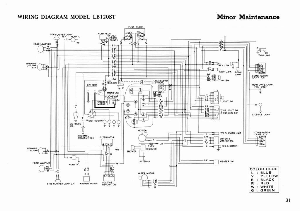
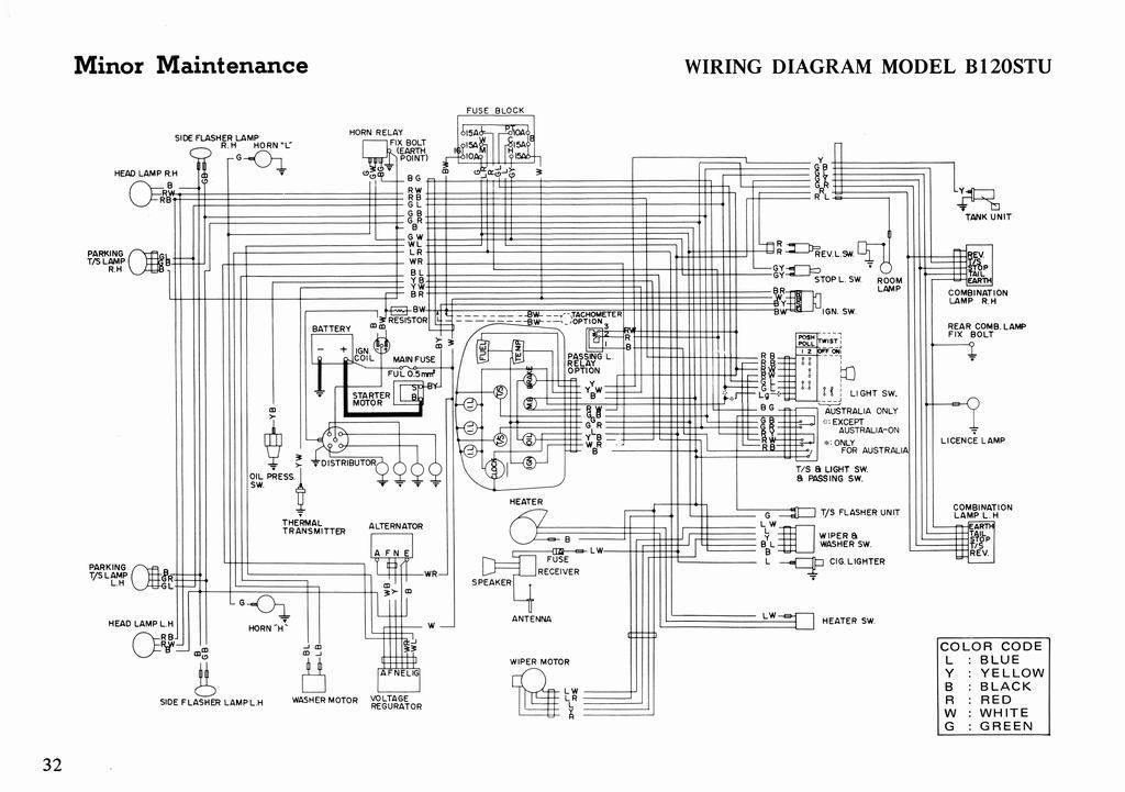
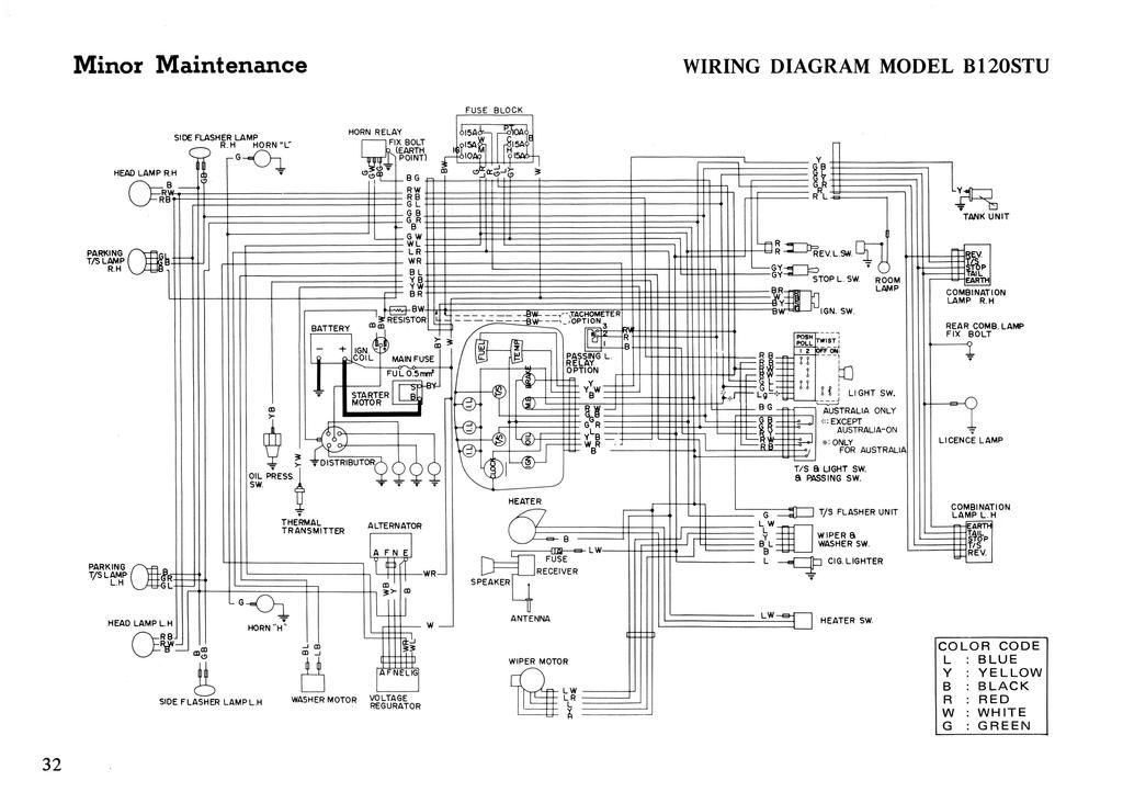
For all countries except Japan. The only difference is that the RHD diagram shows an optional ignition switch wiring for Australia.
LB120ST (LHD, Standard, 4-speed) - 1974 Export Pickup Owner's Manual (pages 31):
http://i297.photobucket.com/albums/mm219/ddgonzal/Datsun%201200/owners_manual/1974/31.jpg 1024 x 722
B120STU (RHD, Standard, 4-speed) - 1974 Export Pickup Owner's Manual (pages 32):
http://i297.photobucket.com/albums/mm219/ddgonzal/Datsun%201200/owners_manual/1974/32.jpg http://i297.photobucket.com/albums/mm219/ddgonzal/Datsun%201200/owners_manual/1974/32-400.jpg 6 megapixel version (3304 x 2328)
Australia
1978 Australia 1200 ute
3 parts each 656 x 1280 (Total size 1968 x 1280)


 1968 x 1280 (2.4 megapixel)
Other RHD
Differences between 1978 Australia and 1978 other RHD
Horn "Low" is optional in Australia * standard for other RHD countries.
Transmission switches * Australia: Spade connectors for Back-up lamp switch * Other RHD has Round multi-connector to: ** Spade connectors for Top Gear switch ** Spade connectors for Back-up lamp switch
Other RHD has: * T/O Cut Solenoid * Vacuum Cut Solenoid * Speedometer has speed switch and attached SW amplifier * Heater is optional * Dimmer dash illumination switch ** Has usual six-connector rectangular connector ** Has additional 1-spade wire for Twist Control ** Two-position: Normal and Dim (not continously variable)
LHD
Left-hand Drive 1978 B120 has these differences from RHD: * Cigarette lighter is not illuminated
Otherwise may be identical as far as colors and wires, but presumably the length of many wires differ.
B122
Early B122 [need diagram]
Late B122 Sunny Truck from October 1989


 3 x 512x658 (poor scan)
Included in 整備要領書 Service Manual Nissan Sunny Truck 1989 October R-B122 type, R-GB122 type 1989 -- see Repair_Manual#Japanese
http://i297.photobucket.com/albums/mm219/ddgonzal/Datsun%201200/Parts/th_R-B122.jpg http://i297.photobucket.com/albums/mm219/ddgonzal/Datsun%201200/Parts/th_R-B122-B.jpg
B210
B210 was the 3rd gen Sunny, marketed as Sunny in Japan, B210 in North America and as 120Y in the rest of the world.
120Y
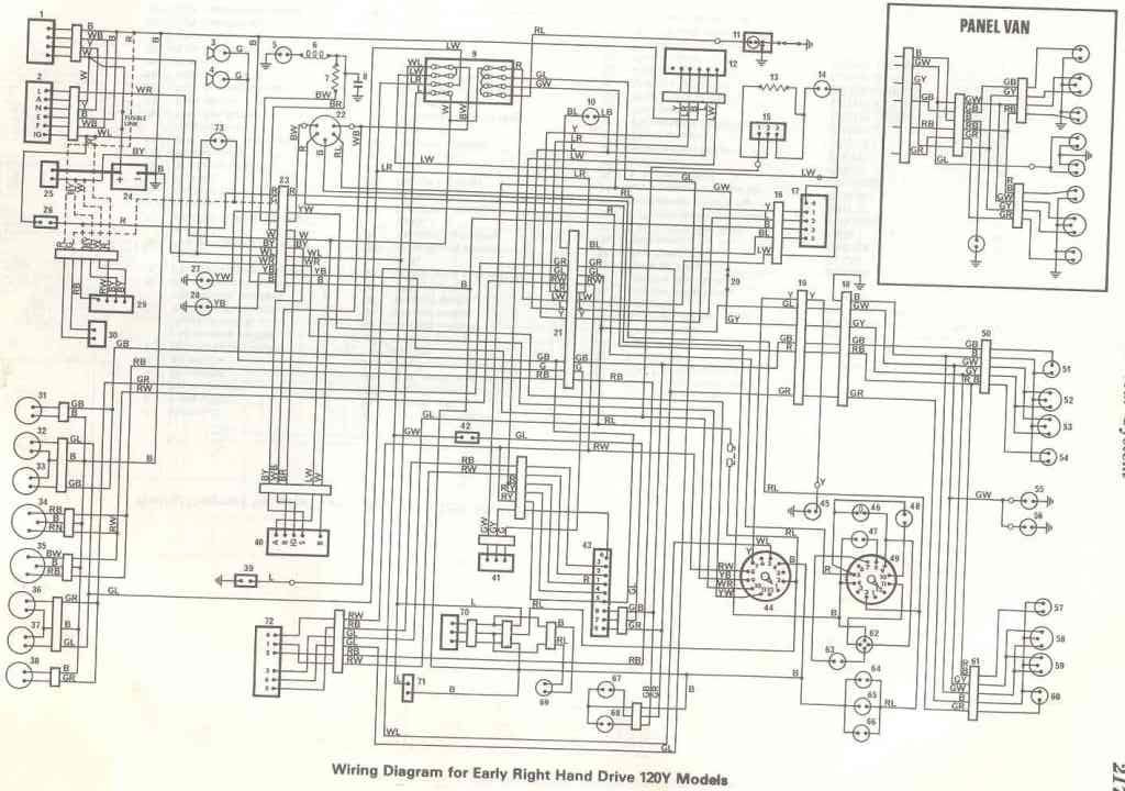
Wiring Diagram for Early Right Hand Drive 120Y Models

http://i297.photobucket.com/albums/mm219/ddgonzal/Datsun%201200/wiki/9665_4ad05503408e8_.jpg
KEY
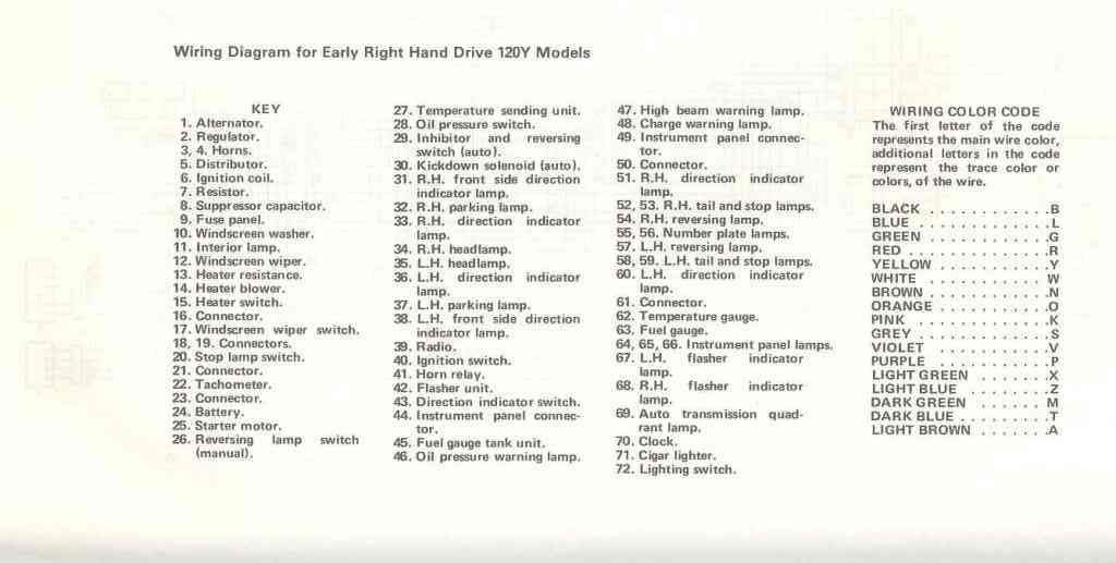
1. Alternator 2. Regulator 3,4. Horns 5. Distributor 6. Ignition coil 7. Resistor 8. Suppressor capacitor 9. Fuse panel 10. Windscreebn washer 11. Interior lamp 12. Windscreen wiper 13. Heater resistance 14. Heater blower 15. Heater switch 16. Connector 17. Windscreen wiper switch 18, 19. Connectors 20. Stop lamp switch 21. Connector 22. Tachometer 23. Connector 24. Battery 25. Starter motor 26. Reversing lamp switch (manual) 27. Temperature sending unit 28. Oil pressure switch 29. Inhibitor and reversing switch (auto) 30. Kickdown solenoid (auto) 31. R.H. front side direction indicator lamp 32. R.H. parking lamp 33. R.H. direction indicator lamp 34. R.H. headlamp 35. L.H. headlamp 36. L.H. direction indicator lamp 37. L.H. parking lamp 38. L.H. front side direction indicator lamp 39. Radio 40. Ignition switch 41. Horn relay 42. Flasher unit 43. Direction indicator switch ... tbc ...
WIRING COLOR CODE
The first letter of the code represents the main wire color, letters in the code represent the trace color or colors, of the wire.
BLACK B BLUE L GREEN G RED R YELLOW Y WHITE W BROWN N ORANGE O PINK K GREY S VIOLET V PURPLE P LIGHT GREEN X LIGHT BLUE Z DARK GREEN Z DARK BLUE T LIGHT BROWN A

http://i297.photobucket.com/albums/mm219/ddgonzal/Datsun%201200/wiki/9665_4ad0550f0c87c_.jpg
¤